Cette
page était sur le site de PA9OK; mais le lien ayant
disparu, j'ai reproduit ici l'article que j'avais
conservé. (F5AD)
********************************
|
|
|
|
| |
| An
experimental eight-shaped loop for HF |
| |
| By Otto
Kühn / PA9OK |
| Some time has passed since
I worked on the eight-shaped magnetic loop (by PA0FRI).
Many experimental designs were tested and not all of them
were successful. After all, all those experiments were
meant to gain experience for building a double loop for
HF with a reasonable chance of success. |
| |
|
|
| |
Why
an eight-shaped magnetic loop antenna?
|
| |
The idea behind the double
loop is that two properly polarised magnetic fields
enhance each other and because the two loops are in
parallel, the impedance at the tuning point will be lower
and the bandwidth larger compared to a single loop. The
narrow bandwidth of a single loop, just a few Kc, makes
tuning difficult. A loop’s perimeter, in this case the
sum of both perimeters, determines the antenna’s
inductance. This should be borne in mind when calculating
the size of the coupling loop. The two loops, exactly
equal in size and calculated for a certain frequency, are
tuned to the frequency band by a capacitor. The loops are
180º out of phase relative to one another.
These were some fundamentals. The experiments with the
small eight-shaped VHF loop have shown that its practical
behaviour is in reasonable agreement with theory. |
| |
I do not claim to present
a ready-to-apply project. This text is no more than an
effort to give some suggestions and to show a few tricks
that make it all a little easier. Conduct your own
experiments and try to figure out improvements.
It’s all experimental work and what can be nicer than
being able to say in the end: This I have designed
and built myself. |
| |
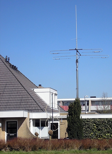
| After having
applied all my calculations, I still feel there must be
yet another factor that should explain why an antenna
with a perimeter less than ¼ lambda works better than
one may expect from calculations based on theory. |
| |
| The experience obtained
from constructing the small double loop was a good reason
to construct the HF magnetic loop described below.
Initially a hexagonal loop was planned, because its
construction from copper tube requires no precise bending
and therefore is easier than constructing a circular
loop. However, I got a generous gift of insulated tube,
Ø 22 mm, made of soft copper and of a useful length.
This implied a considerable reduction in cost. As a
consequence, however, I had to venture on bending tube
once again and this time it was tube of a relatively
large diameter. |
| |
| THE LOOP |
| |
| The tube was made of soft
copper with a diameter of 22 mm, which was covered by a
protective layer of plastic. This kind of tube is usually
supplied in lengths of 10 m on rolls of a diameter of 80
cm. |
| |
| How does one know what
loop diameter or tube length is needed for the required
frequency? There are programs (loop calculator) that
produce this information simply and quickly, but actually
the basic calculation is of a convenient simplicity. |
| |
Here is an
example for 14,200 MHz:
Wavelength lambda = 300 / 14,200 = 21.13 m
¼ lambda = 21.13 m / 4 = 5.28 m
Loop diameter = 5.28 m / 3,14 ≈ 5.28 m / 3.14 = 1.68 m |
| |
| Of course it is possible
to use a loop calculator, for example if for some reason
the loop size has to be a little smaller or if the
desired tube length is not available. The applied
material and the tube diameter also affect the result.
This and much more is conveniently calculated by such a
program. You may find a good calculator for HF by KI6GD. |
| |
| I
constructed a loop with a perimeter just below ¼ lambda,
because such a loop radiates and receives a vertically
polarised field if positioned vertically. According to
the above calculation, a diameter of 1.68 m would yield a
perimeter of ¼ lambda, so I reduced it slightly to 1.60
m. Thus the perimeter will be 1.60 m x 3.14 = 5.02 m.
Therefore I took a tube length of 5.0 m, which had to be
measured on the roll of 80 cm diameter. A simple trick
did the job. I cut off exactly 5.0 m of rope with a
negligible elasticity and fixed it to the outer side of
the tube using small pieces of self-adhesive tape (see
picture below). In this way the exact length of tube was
obtained in a simple way. Two lengths of tube of exactly
equal lengths were made in this way to construct the two
loops that had to be stacked one on top of the other. |
| |
 |
| |
| To obtain a
real circle, I applied the following procedure. First the
tube was bent into a smooth and approximately circular
shape without causing sharp bends. Then a bending
template was made from a plank of approximately the same
thickness as the tube diameter. It was cut into two parts
by removing a circularly curved strip (see picture). The
width of the strip was equal to the tube diameter. With
two clamps the two pieces of wood with a part of the tube
in-between could be kept together, thus forcing the tube
into a circular shape. The radius of the strip was
slightly smaller than the radius of the planned loop,
because after releasing the clamps the elasticity of the
tube would cause the tube to spring back a little bit.
For this reason, the tube should be bent a little beyond
its eventual curvature in the process. |
| |
|
|
| |
| Now the clamps (see
picture) were used to fit the tube snugly into the
template. This goes without extreme force because of the
soft copper. The clamps were released, the treated part
of the tube was moved just out of the template and the
entire procedure was repeated until the loop had become a
circle and both ends met. |
| |
|
|
| |
| The result was a set of
two identical loops (see picture). |
| |
| Of course both loops had
to be connected. Two 22 mm brass or bronze compression
fittings were be applied. Before connecting the loops, I
modified the fittings a little. In the middle of one side
of the hexagon I drilled a hole of 4.8 mm diameter and
cut an M6 thread inside it. |
| |
A 6 mm brass stud was
screwed in and brazed at both ends. The reason for this
was that the plastic casing of the vacuum capacitor would
be mounted at this point and at the same point both loops
would be held together. The weight of the vacuum
capacitor, the stepper motor and the stress on the
connection of the two loops was expected to cause some
strain on this point. Hence those who might wish to copy
the system should pay careful attention to this
connection and to using good quality material.
After this modification the loops could be connected.
First the gland nuts and the rings of the compression
fittings were put over the tube ends and the nuts fixed
tightly. Now neither the nuts nor the rings could be
removed from the tube anymore. However, with this
construction it remains possible to separate the tubes
from the respective fittings, but the rings will remain
in position. This may be convenient in view of possible
transport of the antenna. |
| |
|
|
| |
| Now a key (
a wrench would also work) was put to the hexagon of the
coupling piece and the nuts were fixed tightly using a
second key. The nuts and the hexagon differ in size and
hence the key sizes should differ accordingly. Those who
copy the construction should make sure that the studs of
both loops will end up opposite each other (see picture). |
| |
 |
| |
| To fix the
tubes and fittings firmly to the PVC casing that was to
harbour the capacitor, a plastic ring of Delrin ® was
inserted into its upper end. Delrin ® is a good
insulator, does not absorb moisture and hence will not
affect the capacitor. If the casing is really moisture
proof, other materials such as nylon may be an acceptable
alternative. Inside the white ring (picture) the studs
with nuts and rings are visible. The leads to the vacuum
capacitor were connected to these points. |
| |
| The
tuning capacitor |
| |
| The vacuum tuning
capacitor was from Jennings. It has a range of 10-500 pF
and is rated for 15 kV and 65 A. This capacitor became
available to me by chance. Both casing and mounting have
been adapted to this capacitor. |
| |
|
|
| |
| Using an ordinary variable
capacitor is also possible if the plate distance is
sufficiently large to accommodate the high voltages
across the capacitor. Preferably use a split-stator type
because of the high currents that may develop. Because of
the construction of the coupling ends, positioning of
such a capacitor is a rather simple matter. The studs are
simply positioned downwards and thus can conveniently
accommodate the capacitor (see picture). |
| |
|
|
| |
| The casing for the
capacitor was made of a 350 mm long piece of PVC tube
with 115 mm diameter. To connect capacitor and stepping
motor and to fix both inside the casing, it was necessary
to use a lathe to make a properly sized adapter. Again I
used Delrin ® as a material. The connection between
capacitor and stepping motor consists of a universal
joint with a ceramic separation disc with steel springs
that can compensate for any difference in moving
direction. It also acts as a galvanic separator between
motor and capacitor. |
| |
 |
| |
| Cross-section of the
casing of the vacuum capacitor, the adapter, the joint
between drive shaft and capacitor, the stepping motor and
other components. |
| |
 |
The lower end
with stepping motor. |
|
| |
|
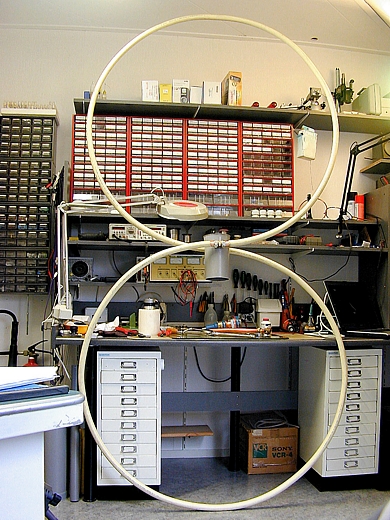 |
The first test set-up (picture)
in the shack shows the impressive size of the
eight-shaped magnetic loop. On the picture it
still lacks the coupling loop. The coupling
loop was bent from 8 mm soft copper tube,
positioned inside the big loop and insulated from
it.
Because two loops on top of each other are
applied, the sum of the two perimeters is applied
as a substitute diameter in calculating the size
of the coupling loop.
Example:
Total perimeter = 5m x 2 = 10m
Substitute loop diameter = 10m / 3.14 = 3.18m
Coupling loop diameter = 3.18m / 5 = 0.64m
Observe that the diameter of the coupling loop
is twice as large as for a single magnetic loop!
|
| |
|
|
|
|
|
|
| |
|
|
| |
| This eight-shaped magnetic
loop, made from two lengths of tube of 3.70 m and 22 mm
tube diameter resonated at 7.0976 MHz and 14.201 Mhz with
an SWR of 1:1.0 and an impedance at the feed point of at
least 52 Ω. These two tube lengths are actually a bit to
short to be used with 7 Mhz but this was all I had and I
really wanted to be able to work on this band.
Surprisingly after the first CQ, CQ I immediately got a
response. |
| |
| Different test QSOs in the
40 meter band with the antenna in the shack with HB9, SP,
DL and EA yielded reports ranging from 5.7 to 5.9. HB9ESS
even gave me 5.9+. Thanks Chris. |
| |
| Further
testing, such as on working at various bands, bandwidth,
capacitor value and radiation behaviour will follow. |
| |
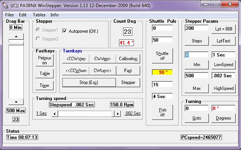
| To control
the stepping motor I used a program with hardware
developed by Lodewijk Baars, PA3BNX. This program that
has many possibilities, runs on every notebook or PC and
if necessary even on a DOS machine. |
| |
 |
| |
| This program
will control the stepper motor which is connected to the
variable capacitor of the antenna. For CAT controlled
transceivers a calibration table is included to lock the
stepper. Pictures of the circuit diagram are included in
the software. Click on info for more information after
installation of the program. |