Cette page était
sur le site de W0LMD; mais le lien ayant disparu, j'ai reproduit
ici l'article que j'avais conservé. (F5AD)
*********************************
A NEW CONCEPT IN BIG YAGIS
W7CY - "CapYagi
TM
| Three dimension capacitive loaded
design shrinks the size without shrinking the
performance. The CapYagi
TM minimizes tower, rotor and real
estate requirements. Shortened elements allows greater
front to back than a full size yagi with virtually none
of the losses associated with use of lumped constants or "magic"
linear loading.
An article about the
remarkable qualities of the W7CY cap yagi appears in the
ARRL publication "Low Band DXing" by
ON4UN.
|
 |
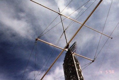
| A 75 meter yagi consists
of an 80' cross boom (left to right) with two 36' end
spreaders. A spreader 12' above the boom supports the
center of the active elements, Wire elements stretch from
the top spreader to the tips of end spreaders. The
tapered aluminum end spreaders are insulated at the
center and act as capacitance hats for the elements.
The antenna is configured
as a driven element and reflector. The driven element is
physically 111' 9' +/- long and the reflector is 116' +/'
long. The difference is in the length of the insulated
section at the center of the end spreaders. This is
adjustable for tuning.
Effective antenna height
is gained by raising the center of the elements.
|
 |
| The antenna is designed
to withstand 120 MPH winds. It weighs about 250
pounds and has only 12 sq. foot wind loading.
Mounted on a U.S Tower
HDX 589. It turns easily with an Orion rotator.
A trussed structure is
used for maximum strength at minimum cross sectional
area. Structural design was done by Kurt Andress - K7NV
- using his commercially available YS software for the
end spreaders and Finite Element Analysis software in
conjunction with a custom beam/column buckling software
for the guyed cross boom structure.
|
 |
| The front to back
ratio is in excess of 20 db between 3770 to 3805.
Computer models show gain at 4.1 dBd in free space.
Feed point impedance is 50 ohms at resonance. The antenna
is tuned to 3789 with a 2:1 SWR from 3750 to 4000
(The effects of the reflector diminish above about 3850
with gain dropping off to about 2 dbd with 5 db front to
back at 4mHz). The antenna is fed directly with 50 ohm
coax through a 1:1 balun. Electrical design was done by Rod
Mack - W7CY - using custom software for phase
analysis, AO and NEC wires for pattern and tuning
parameters. Installed resonance was 3780 - just 9 kHz
below computer predictions. Virtually no tuning was
required!
|
 |
Copyright © 1998 by Rod Mack - W7CY. All
rights reserved.
Updated January 7, 2004