Cette page était sur le site de
G1MFG; mais le lien ayant disparu, j'ai reproduit ici l'article
que j'avais conservé. (F5AD)
********************************
G1MFG.com
Home of the cheapest synthesised ATV transmitters and receivers in Europe!
Modification Zone
This page contains various modifications for our transmitters and receivers that have been developed independently by our customers (unless otherwise stated). Modifications include:
Notes in brackets after the mods indicate who came up with it, and whether we've checked it. Please feel free to suggest any other mods you've come up with!
WARNING: technically speaking, doing any of these modifications will void your warranty. But we're realists and if you get a failure after, but not caused by, doing these modifications, we'll be very sympathetic. Please note that one or two of the modifications will void your guarantee, but these are clearly identified on this page.
| Modification add an S-meter to your 23cm receiver |
We've finally found out how to add an S-meter to the 23cm receiver. And it's easier than we thought! Almost all the circuitry is built into the receiver module, but a vital link is missing. The S-meter circuit outputs 1V for no signal, rising to about 5V for absolutely deafening.
First, the missing link. It's a bit difficult to see in this photo, but if you open up the receiver can you should be able to find two pads either side of a 'wall' (labelled A and B in the photo below). There's just enough room under the 'wall' to solder a tiny link wire between the two pads.
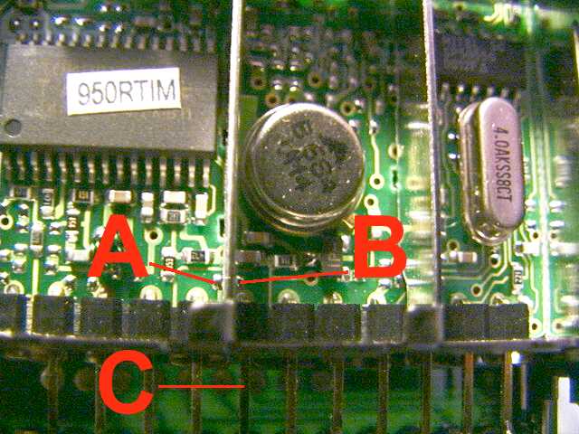
The S-meter output will now appear on the pin labelled C in the photo.
Regrettably, we don't know the output impedance of the S-meter drive. Also, it's a little inconvenient in that it starts at 1V. So we've lashed up the following offset-nulling circuit:

The 1k resistor is used to forward-bias the two diodes to about 1.4V or so, to provide a voltage reference. The diode type isn't important - you can use any general purpose silicon signal diode (1N914, 1N4148 etc.).
The preset pot provides a variable voltage to the negative side of the meter, lifting it up to a maximum of 1.4V above ground. The positive side of the meter should be connected to the pin marked C in the above photo. Ideally, use a 4V meter - but you can use any low-current meter (provided you include the appropriate series resistance, of course). We use an old multimeter which just happens to have a 4V DC range.
Switch on the receiver with no input signal. Adjust the pot until the meter reads zero. Now apply a signal - hey presto, the meter moves according to the signal strength. Very useful for aligning your beam accurately!
(G1MFG)
John, G3RFL has characterised his receiver's S-meter output for various RF input levels using a 1271MHz blank carrier. All voltage measurements were made using a DVM (i.e. it didn't significantly load the output pin).
Input |
S-meter pin volts |
Comment |
-120dBm |
1.32V |
No discernible signal |
-110dBm |
1.34V |
|
-100dBm |
1.36V |
Noisy signal on screen |
-90dBm |
1.45V |
|
-80dBm |
1.65V |
Screen gone black by this point [i.e. P5 - G1MFG] |
-70dBm |
1.92V |
|
-60dBm |
3.66V |
|
-50dBm |
3.82V |
|
-40dBm |
4.15V |
|
-30dBm |
4.23V |
AGC fully saturated - no increase in voltage for increase in signal strength |
(G3RFL)
| Modification to improve power output of transmitters |
Let's start with a really easy one. Although the transmitters will run from 12V, maximum power output is available with a power supply of 15V or more. Don't run the modules off more than about 18V though. And remember: tip positive!
(G3TQA - checked out by G1MFG)
| Increasing the 13cm transmitter output to 30mW |
There is a rumour circulating that the power output of the 13cm transmitter can be increased to 30mW or possibly a little more by removing the surface mount resistor beside the two capacitors in the output socket compartment of the Tx can. Please go carefully - there isn't much room to make a mistake.
This modification will void your guarantee.
(G1MFG - checked out by G8CKN)
| Modification to improve received picture quality (1) |
This modification is only directly suitable for the 23cm receiver. The 13cm receiver circuit layout is different.
This is another easy one, but it can improve the receiver by a whole P-grade! Just add a 470p capacitor (either a surface mount type or a normal ceramic disc) in the position shown in the following picture.

Note that although adding this capacitor significantly reduces the onscreen noise, it also reduces the colour subcarrier level. A very few monitors will refuse to display colour when this capacitor is added. Try a lower value - 220p or 100p - if necessary. The noise attenuation less pronounced with smaller capacitors, but on the other hand so is the reduction in colour subcarrier. Suck it and see.
(G8CKN - checked out by G1MFG)
| Modification to improve received picture quality (2) |
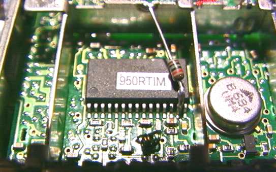
This modification is only suitable for the 23cm receiver because the13cm receiver is different internally. Please note that you'll need good eyesight, a small soldering iron and very steady hands to accomplish this modification. It's included as standard on the Gold receiver.
We don't yet know why this one works, but the effect can be quite dramatic. Just solder a 10k resistor between ground and pin 14 of the 30 pin chip inside the tuner can. If possible, use a 1/16 watt resistor because they're smaller and the leads are thinner. There isn't much space to work there, so be careful. If you orient the receiver so that the sockets are on your left, then pin 14 is one in from the right of the 'bottom' row of the IC pins.
Like we say, we haven't researched this one in great detail yet. It works best when combined with the add-a-capacitor modification described above.
Look what these two modifications can do! |
|
|
|
| Off-screen shot of GB3AT received at G1MFG QTHR on unmodified receiver. You can't see the frame rolling but take my word for it - it did! | Same receiver with the two "improve picture quality" modifications done. A perfectly steady picture with much less noise. |
Click on either picture for a close-up view. |
|
For some reason, some receivers go a little off-tune when this modification is applied. This just means that the DIP switch/frequency chart becomes a little inaccurate - play around with the bottom two or three switches until you find the offset required for best reception.
This modification will void your guarantee.
| Modification to add CCIR pre-emphasis and de-emphasis |
When using the transmitter with other hams we've noticed that the colour subcarrier is a bit weak. This is caused by the lack of CCIR pre-emphasis on the transmitter. GW3MEO suggests adding the following networks to the transmitter and/or receiver to add the correct pre-emphasis characteristics.

(GW3MEO - not yet verified by G1MFG)
Poor man's fix for Tx pre-emphasis (suggested by Clem, G3UGR) - put a 150p capacitor between the wiper and 'hot' end of the deviation pot on the main PCB. Use this pot and the one inside the RF can to balance the overall deviation (RF can pot) and HF boost (main PCB pot). We haven't tried this yet but Clem says "it seems to do the job quite well".
| Modification to improve sound demod sensitivity |
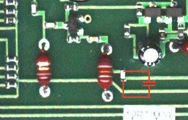
The sound demodulation on the G1MFG receivers is already pretty good, but it can be made even better by adding an 82p capacitor across the one shown here. Note that this picture shows the 23cm receiver - we haven't checked it out on the 13cm one yet but it should work OK.
(G1MFG - checked out by G8CKN)
| Modification to run volts up the receiver co-ax to power a pre-amp |
Another easy one. Just supply volts to the receiver can pin nearest the RF socket. Maximum 18V, 250mA. We suggest you include a 100mA fuse or some other form or protection because if you short the co-ax you CAN do SERIOUS damage to the receiver (some of the very thin tracks on the RF PCB will burn out and they're a pig to repair).
(G1MFG)
| Modification to improve the gain control range on the receiver |
Just replace the 10k pot on the receiver PCB with a 1k one. It gives a MUCH smoother gain control!
(G8CKN - checked out by G1MFG)
| Modification to change the second Rx sound channel to 5.5MHz |
We've heard this one described but we haven't checked it out. To change the 6.5MHz sound demod to 5.5MHz, replace the 6.5MHz ceramic filter with a 5.5MHz one (they're readily available), add about 18p across the existing tuning capacitor (see arrow) and tune the transformer (CAREFULLY!) until you can resolve the 5.5MHz sound.

This modification will void your guarantee.
(G8CKN, not checked by G1MFG)
| Modification to increase the 6MHz subcarrier sound level |
We've found that the -30dBc sound subcarrier level isn't quite enough to open the squelch on some repeaters. This modification is tricky but it will increase the subcarrier level to about -20dBc.
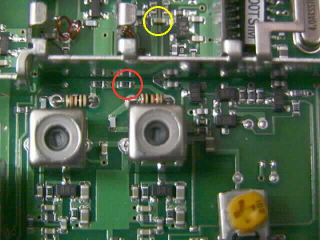
Open up the transmitter can. Solder a 10n capacitor (either leaded or surface-mount) across the resistor circled in RED in the picture. Be careful - there's very little space to play with in there!
You can also increase the 6.5MHz sound subcarrier level by soldering another 10n cap across the resistor to the left of the one indicated with the red circle. We believe (but have not confirmed) that you can disable the 6.5MHz sound oscillator by removing the resistor to the left of the one indicated with the red circle, or snipping one lead of the left-hand 100 ohm resistor (just above the left-hand variable inductor).
(G8CKN - checked out by G1MFG)
This modification will void your guarantee.
| Problems with frame lock on transmitted video |
This isn't actually a modification yet - just an acknowledgement of something we're looking in to. We've had reports of poor frame lock (vertical hold) on signals sent by our 23cm transmitters. It seems to be more of a problem when the deviation is turned up high (e.g. to work into a satellite receiver).
We haven't fully identified the cause of this effect yet, but a modification will be posted here as soon as we find out the reason and develop a cheap and easy fix. It seems that the low frequency response of the 23cm transmitter is a bit poor. We think one of the reasons is that the capacitor which couples the video into the PLL varicap is too low in value.
A suggestion which does give a partial fix is to carefully solder a 3n3 or 3n9 capacitor across the capacitor circled in YELLOW on the above picture. Any larger value of capacitor will probably prevent the synthesiser from locking up (symptom: doesn't transmit on required frequency, or bounces between the required frequency and some other indefinite frequency). Please note that this is a tricky modification and will void your guarantee.
We are still looking in to this problem.